Whether in recording programs or synthesizers, you’ll encounter several filter types
It used to be that the only filters we had were the tone controls on consumer hi-fi systems, and guitar amps. You can think of filters as combining amplification and attenuation—they make some frequencies louder, and some frequencies softer. Filters are the primary elements in equalizers, the most common signal processors used in recording. Equalization can make dull sounds bright, tighten up “muddy” sounds by reducing the bass frequencies, reduce vocal or instrument resonances, and more.
Digital technology has made many new types of filters possible. This is because hardware-based filters require precise, relatively inflexible combinations of components that can do only a limited number of tasks. (One of the few that bucked this trend, “The Multiple Identity Filter,” was a DIY project I wrote up for Keyboard Magazine back in the 80s. It was hideously complex, and had more switches than a railroad station.) In fact, with the first Moog modular synthesizers, a bandpass response required patching lowpass and highpass filters (which we’ll encounter shortly) in series, so that one attenuated the highs and the other, the lows – leaving a band of frequencies in between the two.
Digital technology has no such constraints. Mess around with the code, and you can change the response curve completely. As a result, many filters now offer several modes of operation, such as high pass, low pass, bandpass, shelving, etc. Software synths and samplers go even further, sometimes offering dozens of filter modes. But what do they mean? How do you choose the right mode for your particular application? And why are these strange filtering objects attracted to “poles”? Let’s investigate.
DIFFERENT FILTER TYPES
Too many people adjust equalization with their eyes, not their ears. For example, once after doing a mix I noticed the client writing down all the EQ settings I’d done. When I asked why, he said it was because he liked the EQ and wanted to use the same settings on these instruments in future mixes.
While certain EQ settings can certainly be a good point of departure, EQ is a part of the mixing process. Just as levels, panning, and reverb are different for each mix, EQ should be custom-tailored for each mix as well. Part of this involves knowing how to find the magic EQ frequencies for particular types of musical material, and that requires knowing the various types of filter responses used in equalizers.
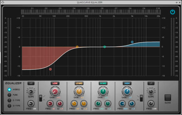
Low pass. A filter with a lowpass response passes all frequencies below a certain frequency (called the cutoff or rolloff frequency), while rejecting frequencies above the cutoff frequency (Fig. 1). In real world filters, this rejection is not total. Instead, past the cutoff frequency, the high frequency response rolls off gently. The rate at which it rolls off is called the slope. The slope’s spec represents how much the response drops per octave; higher slopes mean a steeper drop past the cutoff.
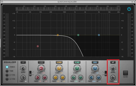
Sometimes a lowpass filter is called a high cut filter. This response is most useful for reducing hiss and excessive brightness on individual tracks. Using it on program material is seldom recommended, because attenuating high frequencies can “muffle” the sound. The shelving response, described later, tends to be more “musical.”
High pass. This passes frequencies above a particular cutoff frequency. Below it, response diminishes progressively with lower frequencies (Fig. 2). The low-cut switches found on consoles, which generally tailor mic response, are high pass filters. This is useful because with “plosive” (“P,” “B”) sounds, mics can produce significant low-frequency energy. The more lower frequencies you can cut below the range of the material being recorded, the better.
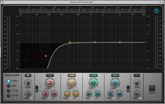
High pass filters with very low cutoff frequencies (e.g., 10 – 20 Hz) are common for removing subsonic energy and/or DC offset from audio that would otherwise use up available bandwidth. High pass filters were seldom used to change the “tone” of program material, but that all changed when DJs started using them to reduce low frequencies progressively to add tension, and then open the filter back up again to full bandwidth.
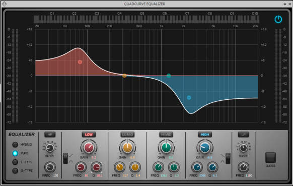
Bandpass/Parametric. This boosts only those frequencies around its resonant or center frequency, while rejecting higher and lower frequencies (Fig. 3).
Typical bandpass filters not only have a variable frequency control, but also a variable boost (makes the frequency range louder) or cut (makes the frequencies softer), as well as the option to vary the range of frequencies that are boosted or cut.
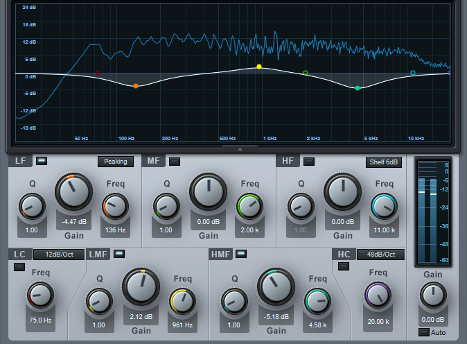
A parametric equalization stage has variable frequency, boost/cut amount (typically ±12 to ±18 dB), and width (the range over which signals are boosted or cut). This is called width, Q, or resonance. When cutting frequencies, a bandpass response is called a notch response.
The parametric stage is considered the most flexible equalizer stage, yet practically speaking, it can be less useful in many applications than shelving or other modes. The parametric excels as an insert effect for individual channels, as you can boost or cut very specific parts of the signal to solve problems. For example, if one tom in a drum part seems too loud, you can zero in on just that frequency and knock it down a bit.
However, using parametrics with program material requires restraint. Generally, broad, gentle changes work best. A little upper midrange boost can add intelligibility to solo instruments and vocals, while a slight dip in the 300 –500 Hz range can reduce “muddiness” and give a track a crisper sound.
A variation on the parametric EQ, the quasi-parametric EQ, is the same as conventional parametric EQ, but lacks the width/resonance control.
OTHER COMMON FILTER TYPES
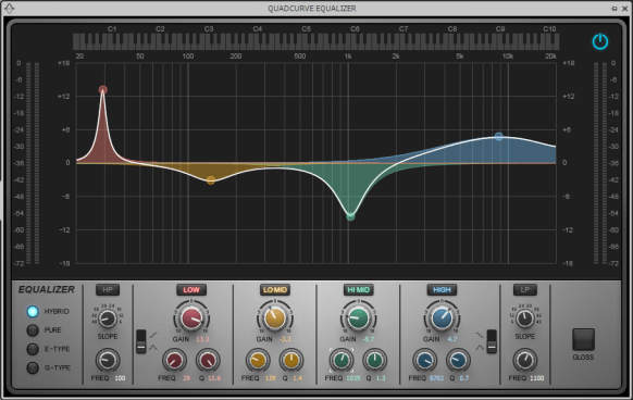
Shelving. The shelving response occurs at the high and/or low ends of the frequency spectrum, and boosts or cuts. The process gets its name because the response first rises or falls, then flattens, like a shelf (Fig. 4).
This response is exceptionally useful for general tone-shaping on individual tracks or program material; I use it a lot for mastering when there’s a general problem with a track (e.g., it was monitored over speakers with poor low-frequency response, so the bass was boosted too much in order to “compensate”). Also, a little high-frequency shelving boost can help give a track more definition and “snap.” Shelving is a broad, gentle type of equalization effect that if used properly, can create a subtle yet important improvement.
Some shelving filters include resonance, which adds a peak around the cutoff frequency when boosting, and a notch when cutting (Fig. 5).
THE POLE POSITION
Some filter modes are simply one of the types above with a different number of poles. The term comes from hardware filters, whose basis is often a resistor/capacitor combination that “tunes” the filter and provides one pole of filtering. However, analog filters don’t just stop the signal past a certain point; instead, the response rolls off gently. A basic 1-pole analog filter rolls off at 6 dB/octave. In other words, the response is down 6 dB an octave above the cutoff frequency, 12 dB two octaves above the cutoff frequency, etc.
Sharper rolloffs require cascading multiple stages. A 2-pole filter combines two 1-pole filters and rolls off at 12 dB/octave, a 3-pole filter at 18 dB/octave, and a 4-pole at 24 dB/octave. Cutoffs steeper than 36 dB/octave are very difficult to implement with analog circuit designs, and not exactly easy with digital. If a software filter has a choice between 12 or 24 dB/octave and 12 dB/octave sounds okay, use it – your CPU won’t have to work so hard.
Note that lowpass, bandpass, and highpass filters can all be multi-pole types.
SPECIALIZED FILTERS
Some filters are designed more to add effects than to create a tonally-balanced track or master recording. These filter types are usually found in synths and samplers.
Resonant filter. There are several types, but the most common is a lowpass filter with a resonance control. This adds a resonance peak in the vicinity of the cutoff frequency. You can use this peak to boost the response at a specific frequency. This gives a sharper sound with synth patches, and gives the “peaky” effect of wah pedals.
Comb filter. This gets its name from the response curve, which has so many dips it looks like a comb. The most common example of the comb filter is flanging, which creates a comb filter, then sweeps it.
Notch filter. Although parametric stages can create cuts, a notch filter is typically narrow and offers a steeper cut. For example, one common application is notching a very deep and narrow cut at 60 Hz to remove power-supply hum.
Formant filter. Designed to mimic the filtering characteristics of the human mouth, format filters impart vowel- or vocal-type sounds onto a signal. They typically are formed by a number of resonant peaks.
Brickwall filters. These don’t roll off the signal gently, but rather, the signal falls off a cliff – a brickwall rolloff of ‑90 dB/octave is not uncommon. These are used primarily at the input of digital systems to prevent signals from interfering with the clock frequency, and at the output to filter out any clock signal from the audio (as well as smooth out stairsteps in the output waveform resulting from the digital-to-analog conversion process). It’s extremely difficult to design analog brickwall filters, and although it’s easier to design digital types, making them sound good is not easy.
Before signing off, remember that equalization should be a way to make something good even better. If you have to use equalization a lot for problem-solving, it’s time to re-evaluate how you record, mix, and master.