This simple project conditions guitar for use with digital processors
When you first pluck a string or strum a chord, guitars produce high initial transients. These can be problematic with digital recording, because if you set an audio interface’s input high enough to accommodate the peaks, then the guitar’s average level is low. The result is more potential noise, less apparent sustain, and the guitar’s level not hitting the “sweet spot” for processors like compressors and amp sims. Although you could place a studio-quality limiter between the guitar and the interface, few limiters have instrument-level inputs, and the transient can cause pumping and other undesirable audio artifacts.
So here’s the solution: a passive limiter that requires no power, costs under $2 in parts, and is small enough to fit inside a small box, guitar cord, or even an audio interface input. Because it’s passive, there are none of limiting’s traditional drawbacks—but hearing is believing, so check out the audio example at the end.
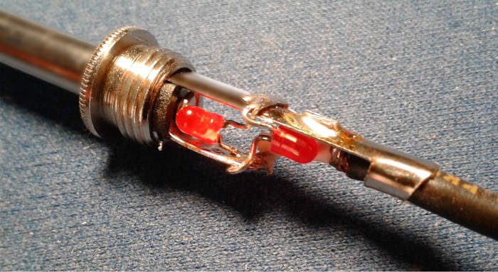
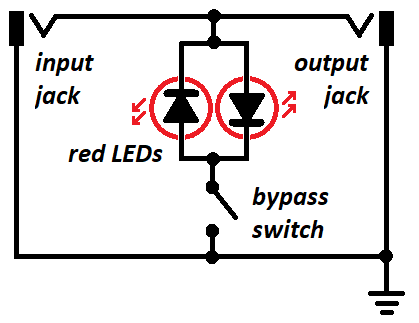
The “secret sauce” is the electrical characteristics of red LEDs. The circuit (Fig. 1) places back-to-back red LEDs across the output’s hot and ground connections. Each LED clips clips positive and negative peaks that exceed about 2.2V. The bypass switch is optional (I always leave the circuit active).
Clipping transients that exceed 2.2V pk-pk doesn’t cause audible distortion because LEDs inherently soft-clip (for the techs in the crowd, it’s because they have junction capacitance that rounds off super-fast attacks). Besides, the transients are too short for our ear/brain to process, even though digital gear can “hear” them.
Fig. 2 shows the difference this makes in a guitar’s waveform. The upper row displays waveforms for the bridge, middle, and neck pickups through the Transient Tamer, while the lower row shows the same waveforms without it. All waveforms have been normalized to the same peak level. Clearly, the upper row has a higher average level.
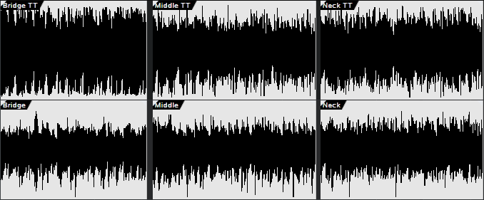
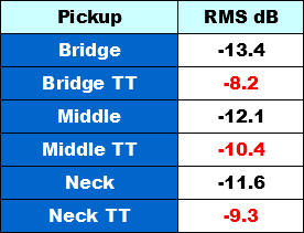
Fig. 3 compares the pickup outputs’ average levels with normalized peaks. With the bridge pickup, the average level is -13.4 dB. Adding the Transient Tamer brings this up to -8.2 dB—an average level increase of over 5 dB! The middle and neck pickup positions have about a 2 dB increase in average level.
Finally, note that red LEDs are best because they have tend to have lower forward voltages (the level at which clipping occurs) than other colors, in the range of 1.8 to 2.6 volts. 2.2 volts is a good compromise value for passive pickups but if you use lower-output pickups or have them further away from the strings than usual, you’ll want the lowest possible forward voltage.
Don’t dismiss this just because it’s so simple—I don’t plug into audio interfaces or digital effects any more without the Transient Tamer. ’Nuff said.