Whether for feeding line inputs, pro audio gear, or driving long cable runs, this box solves multiple problems
Guitars with passive pickups have delicate outputs. Most modern audio interfaces have a high-impedance instrument input to prevent loading down passive guitar pickups, which is a good thing—plugging into a line-level XLR connector is going to mess with both level and frequency response, while plugging into a mic input will result in some combination of noise and/or distortion.
Yet there are still reasons why you might want to plug a guitar into an XLR input, like feeding a studio-quality signal processor. Not everything is a stomp box, and there are a lot of classic hardware processors—from vintage compressors to esoteric items like the Dolby Model 740 Spectral Processor. Or, you might have a pedalboard that needs to feed a live mixing console, and the output isn’t quite hot enough. It could also have a hard enough time pushing signal through yards and yards of cable.
The Guitar-to-XLR Preamp (we’ll call it GXP for short) solves multiple issues. It presents the guitar with a high-impedance input, and transforms it to a low-impedance output. Not only does this preserve the level, it also counteracts a cord’s cable capacitance with long cable runs. Although there are lots of preamps in the world, the GXP is designed specifically to make guitars and basses sound better in the studio. This box will let you patch a guitar directly to a mixing console, drive effects with XLR balanced inputs, and allow for extremely long cable runs without sound degradation. The signal-to-noise ratio is way better than 90 dB, and the frequency response extends past 100 kHz. The overall sound quality improvement can be significant compared to something like a direct box with a transformer.
HOW IT WORKS
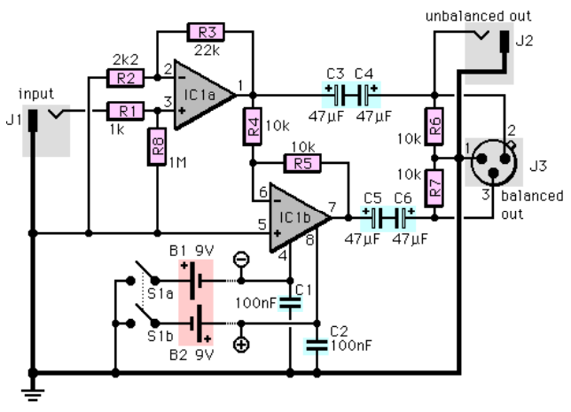
In the schematic shown above, the main ground lines are drawn a little thicker. IC1 is an NE5532 dual low-noise op amp (this chip is used a lot in pro gear because of its excellent specs), however you can substitute a TL082 or TL072 (slightly lower noise than the 082). The TL072 in particular is an interesting choice, because it has a FET-based input stage that’s closer to tube characteristics than a bipolar transistor-based input stage.
IC1a converts the guitar’s output from high-impedance to low-impedance, while adding approximately 20 dB of gain. IC1b provides the additional output needed for balanced line operation. J2 sends the signal to unbalanced inputs, and J3 patches to balanced inputs. Since you can use both outputs simultaneously, the GXP is also an active splitter.
HOW TO BUILD IT
The simplest approach is to mount the parts on a perf board or printed circuit board, which then mounts inside a metal case with a suitable XLR male connector and 1/4” phone jacks. Use metal-film resistors for lowest noise, and a socket for IC1 to prevent heat damage while soldering.
Power the GXP with two 9V batteries as shown, or any bipolar power supply between +5 and +15V. If you’re not going to use batteries, remove them and S1 (which turns the battery power on and off); feed in the external supply at the points marked (+) and (-) on the schematic. The reason for a bipolar power supply is to make sure there’s plenty of headroom.
To use th4e GXP, plug your guitar into J1 using as short a cable as possible, and patch J2/J3 into the console input, processor input, or long cable run.
CUSTOMIZING OPTIONS
To alter the gain, change R3’s value. The amount of gain equals (R3 + 2.2)/ 2.2, with R3 in kΩ. For example, R3 = 22k gives a gain of 11; 100k gives a gain of approximately 45.
J3 is wired with pin 2 “hot,” in accordance with the IEC standard for XLR connectors. However, some maverick gear uses pin 3 as “hot.” You can accommodate this gear by reversing the wires going to J3 pins 2 and 3, but this isn’t absolutely essential unless you’re using the GXP as a splitter.
And that’s all there is to it. Aren’t you glad you know how to solder?
PARTS LIST
Resistors (5% tolerance, metal film preferred for fixed resistors)
- R1 1k
- R2 2.2k (2k2)
- R3 22k
- R4-R7 10k
- R8 1M
Capacitors (35 or more working volts, mylar or polystyrene preferred except as noted)
- C1, C2 0.1µF (100n)
- C3-C6 47µF (tantalum or electrolytic)
Other parts
- IC1-IC3 NE5532, TL082, or TL072 dual op amp
- J1, J2 Mono, open circuit, 1/4″ phone jack
- J3 XLR plug or chassis-mounting male XLR jack (see text)
- S1a+b DPST or DPDT switch
- B1, B2 9-Volt battery (see text)
- Misc. IC socket, perf board, case, wire, power supply, etc.
SPECIFICATIONS
- Frequency response: ±0.1 dB, 10 Hz – 100 kHz
- S/N ratio: >90 dB
- Input impedance: >500k Ohms
- Output impedance: <600 Ohms
- Headroom (+15V supply): >26V peak to peak
- Gain: 20 dB