You’ll like encounter both types of connections, so it’s important to understand their similarities and differences
In today’s studio, you’re likely to find some gear that has balanced analog inputs and outputs, some with unbalanced inputs and outputs, and some with both. Knowing how to interface them properly can make the difference between a quiet, well-behaved signal path, or one with signal loss, mismatches, and general unpleasantness. We’ll give a little theory about the two different types, then some practical interfacing examples.
UNBALANCED SYSTEMS
The typical musical instrument cable is an example of an unbalanced line that has two conductors: one wire is the ground line, which is also referred to as common, earth, shield, or DC return; the other is the signal line, often referred to as the “hot” line. The hot line carries the signal, and is surrounded by a grounded shield that fences out hum and interference (although shielding is not 100% effective). The ground acts as a voltage reference.
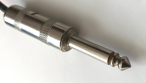
Unbalanced systems with music-oriented gear, like electric guitars and amps, typically use two-wire 1/4” connectors (Fig. 1).
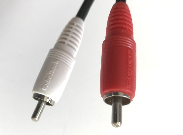
Consumer electronics also uses unbalanced connections, but these are often RCA phono jacks and plugs (Fig. 2). Note that a potential source of confusion is that some consumer gear uses the same type of connector for digital audio.
BALANCED SYSTEMS
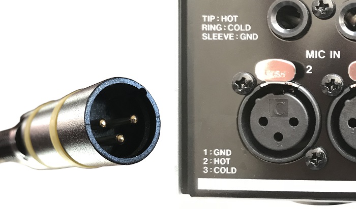
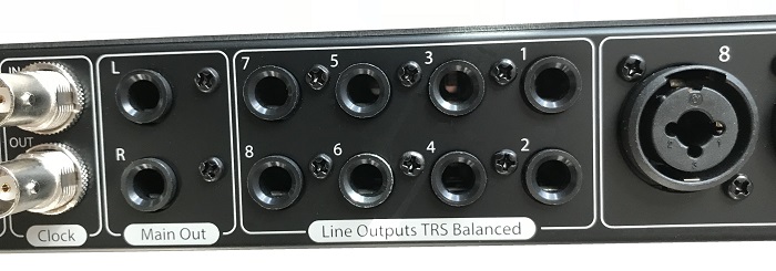
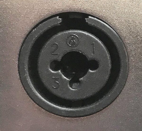
A balanced system adds another signal line (called the “cold” or “neutral” line) to the “hot” signal-line-plus-ground combination in an unbalanced system. Therefore, we need connectors that can accommodate three conductors. The kind that’s most common for mics and pro-level audio equipment is the XLR connector (Fig. 3).
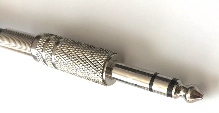
XLR connectors take up a fair amount of panel space, so phone plugs that handle three connectors (called TRS connectors after the three conductors, referred to as tip-ring-sleeve) are often used for balanced connections (Fig. 4).
You’ll often find these in audio interfaces with multiple inputs and outputs, where panel space is tight (Fig. 5).
The reason for the three leads is that the two signal leads carry signals that are identical, but 180 degrees out of phase; thus, as a signal increases in voltage along one line, its mirror image on the other line decreases.
Signals that are out of phase cancel, so it may seem like the balanced system doesn’t make much sense. But here’s the beauty of the system.
A balanced-line signal has to feed a special type of input, found in transformers and certain types of amplifier designs, called a differential input. Thisamplifies the difference between these out-of-phase signals, so it doesn’t matter that they’re out of phase—the combination looks like a normal signal to the differential input.
However, any signal that’s common to the balanced lines—like hum or noise—does cancel, because there’s no difference between the signals on the two lines. Fortunately, the kind of noise and garbage that get into a balanced line system generally spill over both signal lines equally. Since the differential input responds only to the differences between the two signal lines, when the same signal is present on both lines, then there isn’t any difference. So they cancel out, and the differential input ignores them. Some differential amplifiers can reduce these interfering signals (technically called common-mode signals) by over 90 dB—enough to make the interference fade way into the background.
Because of their noise-reducing properties, balanced lines are favored for long cable runs involving low-level signals, such as those generated by microphones. However, balanced lines are generally more expensive than using unbalanced lines, and sometimes balanced lines are overkill for applications like home and project studios. Although you’ll still see balanced lines for microphones, unbalanced lines are usually satisfactory for situations where you have fairly high level signals running a short distance, as is often the case in project studios.
Note that combi connectors (Fig. 6) can accommodate both 1/4” connectors and XLR connectors. These are very handy for audio interfaces, because you can plug in a mic, a guitar, or a line level signal—balanced or unbalanced—and the interface will be able to accept it.
THE BALANCED LINE CONNECTOR WIRING STANDARD
XLR connectors are wired so that pin 1 is ground, pin 2 is the “hot” signal, and pin 3 is neutral. Some people will try to tell you that pin 3 is hot; don’t believe them. There is an international standard that specifies pin 2 as hot. Unfortunately, some manufacturers still wire their gear so that pin 3 is hot. There are two ways around this: go inside the unit itself and switch the pin 2 and pin 3 wires, or buy a special cable that cross-connects these two leads.
With TRS 1/4” phone connectors, the tip is the hot lead, the ring the neutral lead, and the sleeve is ground.