The input impedance of amps and effects can alter tone—so it’s important to know how to measure this parameter.
A passive guitar pickup puts out relatively weak signals, which means that whatever follows the guitar needs to preserve as much of the level and tone as possible. Much of this relates to the impedance the guitar feeds, so let’s consider a simple test for determining the approximate input impedance of amps and effects.
The test itself is simple. You’ll need an analog or digital volt-ohmmeter (VOM), which you should probably have for testing cables and checking your AC voltage periodically (a good digital model should cost less than $40). You’ll also need a steady test tone generator, which can be anything from an FM tuner emitting a stream of white noise to a synthesizer set for a constant tone (or even a genuine test oscillator).
IMPEDANCE BASICS
A deep dive into impedance can get pretty complex, but all we really need are the highlights. An amp or effect’s input impedance essentially adds a resistor from the input to ground, thus shunting some of your signal to ground. The lower the resistance to ground, the greater the amount of signal loss.
The guitar’s output impedance is equivalent to putting a resistor between your guitar and the amp input. The combination works together to impede the signal. If you draw an equivalent circuit for these two resistances, it looks like the schematic for a volume control (Fig. 1).
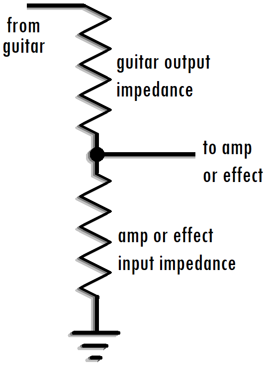
If the guitar’s output impedance is low and the amp input impedance is high, there’s very little loss. Conversely, a high guitar output impedance and low amp input impedance creates a lot of loss.
The reason why a low input impedance “dulls” the sound is because a pickup’s output impedance changes with frequency—at higher frequencies, the guitar pickup exhibits a higher output impedance. Thus, low frequency signals may not be attenuated that much, but high frequencies could get clobbered.
Buffer boards and on-board preamps can turn the guitar output into a low impedance output for all frequencies, but many devices are already designed to handle guitars, so adding anything else would be redundant. So, you need to find out which devices are guitar-friendly and which aren’t, especially with rocessors designed for the studio—there may be enough gain to kick the meters into the red but not a high enough input impedance to preserve your tone.
HOW TO TEST FOR IMPEDANCE
This test takes advantage of the fact that impedance and resistance are, at least for this application, roughly equivalent. So, if we can determine the effect’s input resistance to ground, we’re covered. (Just clipping an ohmmeter across a dummy plug inserted in the input jack isn’t good enough; the input will usually be capacitor-coupled, making it impossible to measure resistance without taking the device’s cover off.)
Wire up the test jig in Fig. 2, which consists of a 1 Meg linear taper pot and two 1/4″ phone jacks. Plug in the signal generator and amplifier (or other device being tested), then perform the following steps.
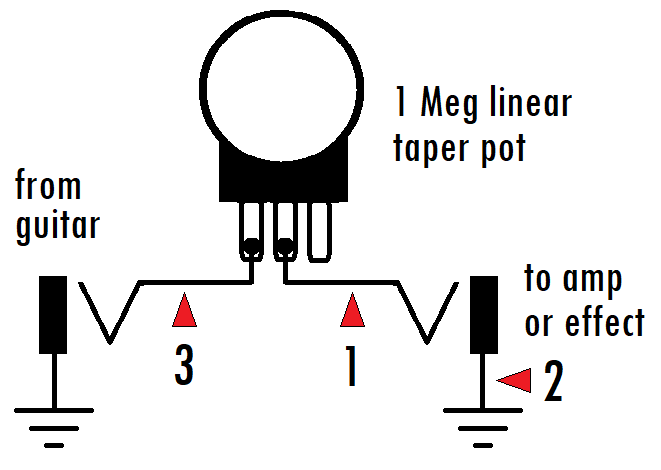
1. Set the VOM to the 10V AC range so it can measure audio signals. You may later need to switch to a more sensitive range (e.g., 2.5V or so) if the test oscillator signal isn’t strong enough for the meter to give a reliable reading.
2. Set R1 to zero ohms (no resistance).
3. Measure the signal generator level by clipping the VOM leads to test points 1 and 2. The polarity doesn’t matter since we’re measuring AC signals. Try for a signal generator level between 1 and 2 volts AC but be careful not to overload the effect and cause clipping.
4. Rotate R1 until the meter reads exactly 50% of what it did in step 3.
5. Be very careful not to disturb R1’s setting as you unplug the signal generator and amplifier input from the test jig.
6. Set the VOM to measure ohms, then clip the leads to test points 1 and 3.
7. Measure R1’s resistance. This will essentially equal the input impedance of the device being tested.
INTERPRETING THE TEST RESULTS
With an input impedance under 100k, it’s probably a good idea to add a preamp or buffer board between your guitar and amp or effect to eliminate dulling and signal loss. The range of 100k to 200k is acceptable, although you may hear some dulling. An input impedance over 200k will likely not produce much of a noticeable change in tone, if any. However, more is not always better; input impedances above approximately 1 megohm are often more prone to picking up radio frequency interference and noise, without offering much of a sonic advantage.
So there you have it. A guitar that feeds the right input impedance comes alive, with a crispness and fidelity that’s a joy to hear. Happy picking—and testing.
Photo credit: Feature image by Michael Henry on Unsplash.com