So what is analog audio, anyway? This quick refresher tells all
Sound consists of variations in air pressure that interact with our ears’ hearing mechanism. The information received by our ears travels to the brain, which processes this information.
WAVES: AIR PRESSURE AND VOLTAGE VARIATIONS
The most common analogy to sound is ocean waves, which are created primarily by wind variations. Like ocean waves, sound waves have crests (the highest point in the wave’s cycle) and troughs (the lowest point in the wave’s cycle). The wave’s height is its amplitude—for example, the crest has a higher amplitude than the trough. The rate at which these waves occur is their frequency.
Acoustic instruments, by their very nature, generate changes in air pressure that we hear directly as sound. Electronic instruments create their sound in the form of voltage variations. These voltage variations must be converted into moving air so we can hear them. This requires a transducer, the name for a device that converts one form of energy into another. For example, a loudspeaker converts voltage variations into air pressure variations (the speaker cone moving back and forth creates these variations). A microphone changes air pressure that hits a thin diaphragm into voltage variations. Other transducers include guitar pickups (which convert the mechanical energy of vibrating strings to electrical energy), and phono cartridges that convert side-to-side stylus motion into electrical energy.
ABOUT WAVEFORMS
All audio, from a barking dog to a symphony orchestra, is a wave with a varying level. Often, the more complex the sound, the more complex the shape of the wave. Visually, when presented on a graph of amplitude (level) versus time, audio looks like a squiggly line that’s called a waveform (Fig. 1).
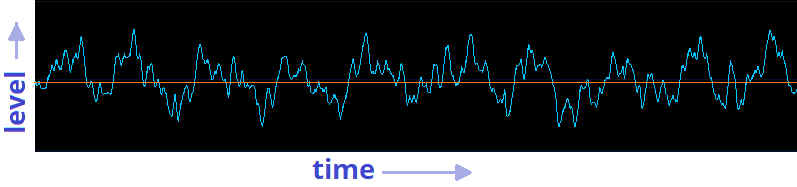
The waveform could stand for air pressure changes, voltage changes, string motion across a pickup, etc. A straight horizontal line represents a condition of no change (e.g., zero air pressure or voltage, as shown by the orange line in Fig. 1), and the waveform’s level references this base line. For example, if the waveform is showing a speaker cone’s motion, excursions above the base line indicate that the speaker cone is moving outward, while excursions below the base line indicate that the speaker cone is moving inward. These excursions could just as easily represent a fluctuating voltage (such as what comes out of a synthesizer) that alternates between positive and negative, or the air pressure changes that occur when you strike a piano key.
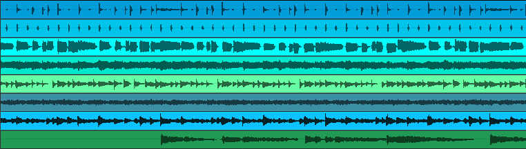
In some multitrack recording programs, a waveform’s visual representation fills in the space between the line that represents audio, and the line that represents a condition of no change (Fig. 2). This makes it easier to see waveform shapes with lots of tracks, because the height for each waveform decreases as you add more tracks. However, the waveform is still a single, varying level.
ANALOG AUDIO RECORDING AND PLAYBACK: VINYL AND TAPE
If we carve a waveform’s outline into a vinyl record, the record’s groove will trace that waveform’s shape (Fig. 3).
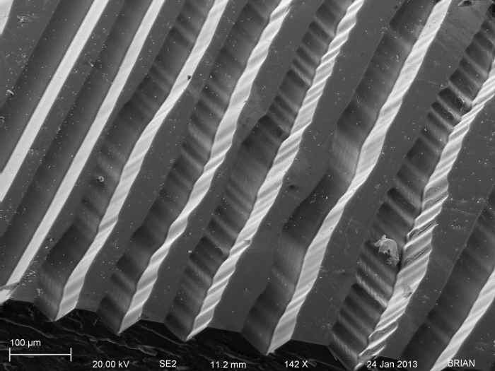
When we play the record, the stylus traces this waveform, and the phono cartridge generates voltage variations that are analogous to the sound’s original air pressure changes. This low-level signal then passes through a preamplifier, and finally a power amplifier, which increases the voltage level enough to drive a speaker. Because the speaker cone follows the waveform motion, it reproduces the same air variations originally pressed into the vinyl record. Notice that each stage transfers a signal in its own medium (vinyl, wire, air, etc.) that’s analogous to the input signal—hence the term, analog audio.
With tape recording, the process isn’t as obvious as carving a waveform into plastic. Instead, a tape recorder’s record head is a transducer that converts audio into magnetic energy, and impresses magnetic patterns on tape that represents the audio waveform. On playback, a playback head converts the magnetic energy back into a voltage, which then works its way eventually to speakers or headphones.
ANALOG AUDIO DRAWBACKS AND LIMITATIONS
Unfortunately, analog audio has multiple flaws, which helped drive the movement toward digital audio. For example, if a vinyl record has pops, clicks, warps, or surface noise, these will be added to the original sound, and you’ll hear them as undesirable audio “artifacts” in the output. A phono cartridge will also add its own coloration; and if it can’t follow rapid changes due to mechanical inertia, distortion will result.
Amplifiers add noise and hum, speakers are subject to various types of distortion, tape recording has hiss and non-linearities (e.g., the output waveform may not look like the input waveform), and so on. So, while the signal appearing at a speaker’s output may be very similar to what was originally recorded, it will not duplicate the original sound exactly, due to the types of errors inherent in analog recording, processing, and playback. When you copy a master tape or press it into vinyl, other problems will occur due to the flawed nature of the transfer process. Another inherent drawback of analog audio is that when you copy an analog recording, the copy’s sound quality will not be as good as the source.
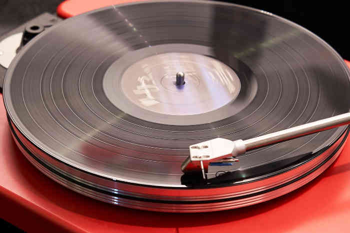
Feature image photo credit: Przemyslaw Marczynski